Companies often call on Matrix to help solve problems that arise during new installations, normal operations, and/or upgrades. This small case study examines how Matrix engineers helped an energy company investigate the cause of catastrophic damage to switch contacts encountered during an upgrade of their coke and by-products facility. Matrix found the root of the problem, weighed potential options, and ultimately provided a successful solution.
 View All Insights
Protecting switch contacts when energizing DC contactors
Brian Haury, PE,
Senior Discipline Manager
Background
Prior to engaging Matrix, the company had ordered a control systems upgrade to the first of two Pusher Machines, which involved adding a PLC to improve operational safety and control of the Leveler Bar.
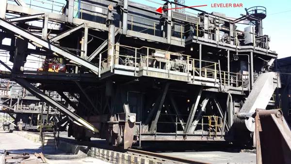
Figure 1 – Pusher Machine
Upon startup and commissioning, several of the 24VDC interposing relays suffered immediate catastrophic damage (see Figure 2). Matrix provided investigative and engineering services to discover the source of the problem and come up with a solution for the failing interposing relays.
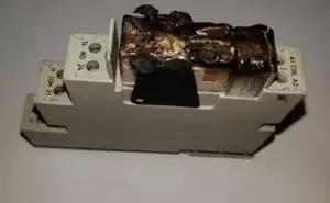
Figure 2 – One of several destroyed interposing relays following one-time use!
Finding the Cause of the Damage
As part of its investigation, Matrix reviewed the schematics for the new and existing Leveler Bar controls and also gathered information on its components. Figures 3-6 illustrate the changes in schematics resulting from the facility’s control systems upgrade.
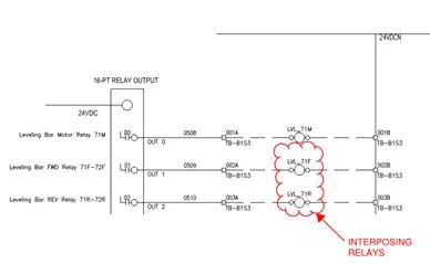
Figure 3 – New PLC digital relay output module
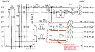
Figure 4 – Leveler Bar control circuit showing where interposing relay contacts were inserted
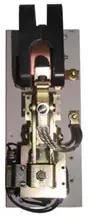
Figure 5 – 250VDC contactor 71F – NEMA size 3, 12” height
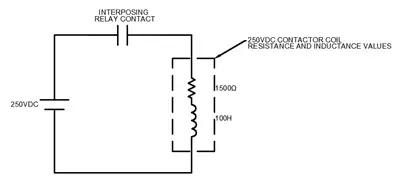
Figure 6 – Resulting circuit
A study of the installation revealed the following was occurring:
- Energizing the DC contactor: Upon closing the interposing relay contact, the voltage across the inductive portion of the DC contactor coil (once the transient effect time has passed, calculated as: 5 x π = 5 x L/R = 333msec), will be 0VDC and the circuit’s current will be: 250V/1500Ω = 0.17A
- De-energizing the DC contactor: Per manufacturer data, the typical “switch-off” time delay for the interposing relay contact is < 7msec. Assuming the longest time delay of 7msec, the resulting voltage across its contacts will be: ecemf = – L di/dt = –100H x 0.17A/0.007sec = -2,430VDC, far exceeding the rated maximum switching voltage of 300VDC. Note: the lower the switch-off time delay, the greater the voltage will be!
Applying a Solution
Once we found the cause of the damage, our goal was to find a way to suppress the excessive voltage and its destructive electric arc across the interposing relay contacts. We considered two options:
Option 1
Matrix first considered the most common solution: install a diode rated for the circuit across the contactor’s coil. In this scenario, when the contact opens, the current generated by the collapsing magnetic field will flow through the diode and back through the coil and continue until the voltage decays to zero. Commonly used names for using a diode in this application are: kickback diode, flyback diode, and snubber diode.
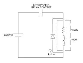
Figure 7 – Option with diode installed
Option 2
The second option was to find a manufactured product for the 250VDC contactor. Fortunately, we were able to special order an arc suppressor from the same company that had manufactured the large contactor. While we could have built an arc suppressor on site, ordering from the same manufacturer ended up being the preferred solution because it was the ideal match for the contactor and of rugged construction. The arc suppressors suppressed the excessive voltage, eliminating the destructive electrical arc that was causing damage to the relays.
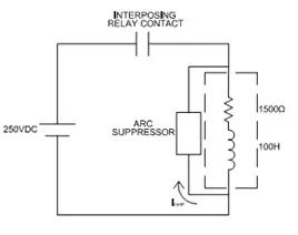
Figure 8 – Arc suppressor in place
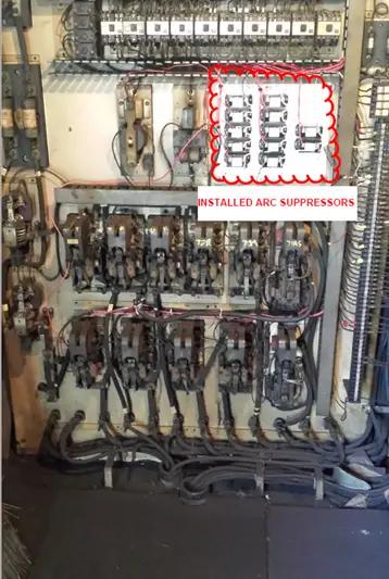
Figure 9 – Panelboard showing Leveler Bar contactors and newly installed arc suppressors
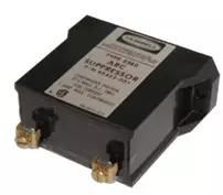
Figure 10 – Switch Contacts
Our Experts Do It Again
When faced with a tough problem, yet another company turned to Matrix for a solution. Matrix engineers applied their vast experience and expertise of electrical physics, applications, and schematic analysis to discover the root of the problem. Installation of the arc suppressors across all contactors controlled by interposing relays proved to be the answer to protect the new control circuit and its components.
This is but one of several success stories where Matrix used its technical resources to provide a cost effective and permanent solution!
Matrix Technologies is one of the largest independent process design, industrial automation engineering, and manufacturing operations management companies in North America. To learn more about our multi discipline engineering consultant services, contact Brian Haury, PE, Discipline Manager.
© Matrix Technologies, Inc.


Brian Haury, PE
Senior Manager

Call
Brian