


Protecting workers from extremely high temperatures, tremendous pressure blasts and shrapnel hurling at high velocity resulting from an arc fault is of paramount importance in every facility’s operation.
An arcing fault is the flow of current through the air between phase conductors or between phase conductors and neutral ground. An arcing fault can release tremendous amounts of concentrated radiant energy at the point of the arcing in a small fraction of a second. An electrical safety program, which contains an arc flash study, is crucial to minimizing injury that could result from an arc flash or blast. The safety program will define the equipment the employee will wear and the manner in which they will safely work.
Matrix Technologies has performed more than 100 arc flash studies, following our rigorous methodology in performing these analyses. Proper evaluation during the course of the analysis results in the correct level of personal protective equipment (PPE) needed to allow employees to work safely around electrical equipment.
The labeling of panels and electrical equipment is required by the National Electric Code (NEC). OSHA, in cooperation with the National Fire Protection Association (NFPA), requires that employers determine and document arc flash information for protection of personnel. The best way to convey this information is through the use of arc flash labels. The labels are the end product of the arc flash study projects that companies undertake to be in compliance. The labeling is the cornerstone of any NFPA 70E safety program; however, there are several project steps prior to printing the labels. Note that the arc flash analysis is only one of the steps of an entire arc flash study.
This article describes the six steps of an arc flash study that Matrix Technologies engineers conduct for meeting Occupational Safety and Health Administration (OSHA) and the recently revised National Fire Protection Association (NFPA) 70E compliance standards. (See accompanying sidebar and references for more information about standards.)
Step 1 – Field Verification and Audit
The field verification and auditing step is critical to the entire study and provides the information that is required to complete the other steps of the project. Prior to arriving on site, the plant will need to supply their existing one-line diagrams and the equipment locations on a plan view drawing. Typically, the Matrix Technologies engineer will spend a few hours reviewing these to familiarize themselves with the equipment and the plant layout. The purpose of this step is for the engineer to verify the validity of the one-line diagram and to obtain additional information required for the computer model.
The engineer will work with one to two electricians to gather and document the data. Personal Protective Equipment (PPE) will need to be worn and applied per NFPA 70E Table 130.7(C)(15)(a), Table 130.7(C)(15)(b), and Table 130.7(C)(15)(c). The personnel need to use these NFPA tables since there are no labels at this point.
The engineer will document the data as the electricians gather it and will prompt the electricians for additional information. In most cases, at the higher voltages, the engineer is no longer “qualified” and will need to stay beyond the arc flash boundary. The project team will conduct their field work when the equipment is in an electrically safe work condition unless the work falls into the variance to this rule as discussed in NFPA 70E, article 130.2(A) Energized Work.
The field work collects data on the following:
- Transformers
- Low voltage/medium voltage (LV/MV) switchgear
- Motor control center (MCC)
- MCC circuit breakers feeding downstream panels
- Distribution panels
- Circuit breakers
- Circuit breaker trip units
- Protective overcurrent relay
- Current transformers (CTs)
- Equipment location on a plot plan
- Conductor length where obtainable
Step 2 – Update One-Line Diagrams
In this step, the engineer takes some of the information gathered during the field work and places it permanently on the drawing. In most cases, this is a CADD drawing and the changes normally take less than one day. This step is not crucial but it is a good practice in order to preserve the data that took significant time and effort to gather. A small amount of effort now will eliminate the need for additional field time in the future during routine maintenance of the safety program.
In general, the update of the single-line diagrams will include the following modifications:
- Update electrical equipment that is not depicted correctly
- Add missing electrical equipment
- Update/add conductor sizing (if space permits)
- Include field work details per the level of detail of the original single line (e. ., transformer ratings, impedance)
Step 4 – Short Circuit Analysis
In this step, the engineer calculates the maximum fault levels at various locations to identify problem areas. A problem exists if the maximum short circuit (SC) rating of a device is less than the available SC current that could potentially flow through that device.
At this point, the short circuit analysis software module is required. In this module, the user selects which bus to fault and the software will automatically perform the calculations. The user will be warned if any devices are underrated (i.e., SC Availability > Device Rating). This technique is implemented on each selected bus in the model. At the end of this SC analysis, the documentation that can be generated is the interrupt duty summary report, momentary duty summary report and the recommendations to resolve any underrated devices.
Step 5 – Protective Device Coordination Study
The next step is to perform a protective device coordination study. The goal of this step is to ensure that the downstream devices (breakers/fuses) clear the short circuit fault before the upstream devices. This effort will minimize the effect of a fault to the smallest area possible.
The Matrix Technologies engineer uses the computer software to generate the graphical representation of the time current characteristic (TCC) curves of the protective overcurrent device under review. To begin, the TCC curves of the protective devices are inserted on to a computer generated TCC graph consisting of a log-log grid with time (seconds) vertical axis and a current (amperes) horizontal axis at a given voltage. The TCC curves for majority of the protective overcurrent devices can be found using the computer software’s data library.
An area of an electrical distribution system will be selected for a particular TCC graph. The engineer will attempt to limit the number of TCC curves on the TCC graph for presentation purposes. Too many TCC curves clutter the log-log grid and make it difficult to read.
The objective of the protective device coordination study is to limit the area of the outage due to a short circuit fault to the smallest practical area . Selective protective coordination is achieved when the protective overcurrent device closest to the fault opens before the upstream protective overcurrent device clears the short circuit fault. The engineer must evaluate the protective overcurrent device pickup settings with respect to the protected circuit’s ampacity or downstream equipment’s continuous current ratings. The engineer also must evaluate the fault clearing time of each protective overcurrent device for a fault at a given location.
The time separation for low voltage circuit breakers, including thermal magnetic circuit breakers, electronic trip circuit breakers and low voltage power circuit breaker is handled differently than overcurrent relays. The objective with low voltage circuit breakers is to avoid the crossing of the TCC curves with no intended time delay.
Selective protective coordination is more of an art than an exact science. The electrical engineer must review the electrical distribution system and the associated TCC curves to determine if selective coordination is possible. There will be instances where two overcurrent protective devices are on the same feeder circuit and therefore selective coordination may not exist. In these instances, the lack of selective coordination will not increase the area of an electrical outage for a fault located on the load side of the feeder circuit and is therefore acceptable.
After this step in the arc flash study, the engineer develops the protective device setting sheets . The protective device setting sheets document the ratings and settings of fuses, thermal magnetic circuit breakers, electronic circuit breakers, low voltage power circuit breaker trip units, and protective overcurrent relays. The protective device setting sheets will also indicate changes to the original settings of the protective overcurrent devices. An additional deliverable includes TCC graphs that were generated as part of the protective device coordination study.
Step 6 – Arc Flash Analysis
In this step, Matrix Technologies engineers determine the incident energy levels, which are then used to define the arc flash boundary and the proper level of PPE. In certain instances where the calculated incident energy is elevated, the protective device coordination study may need to be revisited and readjusted to lower the incident energy levels.
Based on the results of the short circuit analysis and the protective device coordination study, an arc flash analysis is performed on the electrical distribution system under consideration. The arc flash calculations are based on the IEEE-1584 method, which is an acceptable method of arc flash calculations per NFPA 70E-2018. The computer software calculates the bus arcing current based on the bus short circuit fault current calculated from the short circuit analysis. The computer software then uses the bus arcing current to determine the fault clearing time of the protective overcurrent device. Based on equations derived from empirical data, the computer software calculates the incident energy and the arc flash boundary.
The engineer reviews the initial results of the arc flash analysis to determine if the calculated incident energy can be reduced by adjusting the protective overcurrent device settings that were generated as part of the protective device coordination study. Often the incident energy can be reduced by decreasing the instantaneous trip setting of the protective overcurrent device to a value below the bus arcing current. The adjustments are made while maintaining selective coordination between the protective overcurrent devices.
According to Standard IEEE 1584, the 208V and 240V systems supplied by transformers smaller than 125 kVA do not require an arc flash analysis due to empirical data documenting that the bus arcing current cannot sustain itself under these operating conditions. For this situation, Matrix Technologies engineers recommend using the incident energy value of less than 1.2 cal/cm2 to determine the required minimum PPE.
Once the final arc flash analysis is complete, the incident energy reports and the arc flash labels for the electrical equipment are generated. The arc flash labels are affixed to the electrical equipment only after the study’s recommendations have been implemented and the facility has established a safety and PPE program for the plant personnel to follow.
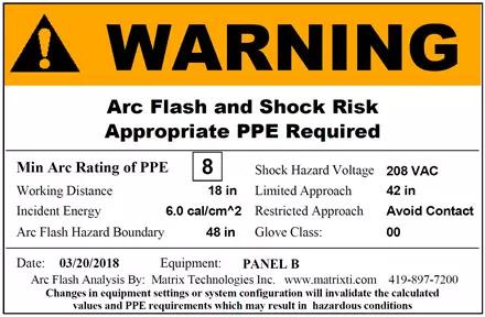
Figure 1: Example of an Arc Flash Label
Matrix Technologies recommends the results of an arc flash analysis be documented on the single line diagrams along with the calculated short circuit current values. As a minimum, the incident energy values should be documented on the single line diagrams. Optionally, the arc flash boundary can also be documented on the drawings.
In Matrix Technologies’ experience, the PPE table found in NFPA 70E can be confusing to some employees and can reference personal protective equipment that may not be provided by the employer. Matrix Technologies recommends to all facilities publish their own custom table that can be laminated and put in various locations throughout the facility such as on electrical equipment, safety boards, hallway walls, etc. This custom table should follow the rules set forth by NFPA 70E and should also reflect the facility safety program that may be more conservative than the NFPA standard. This table can also reflect the PPE that the employer provides and has on hand for the employee and can change as new PPE is developed. An example of a simplified PPE table that Matrix Technologies uses is shown in Figure 2. The simplified table takes into consideration the arc rating of the PPE issued to employees and that employees are not allowed to work in areas where the potential incident energy level is greater than 8 cal/cm2 per Matrix Technologies’ safety program.
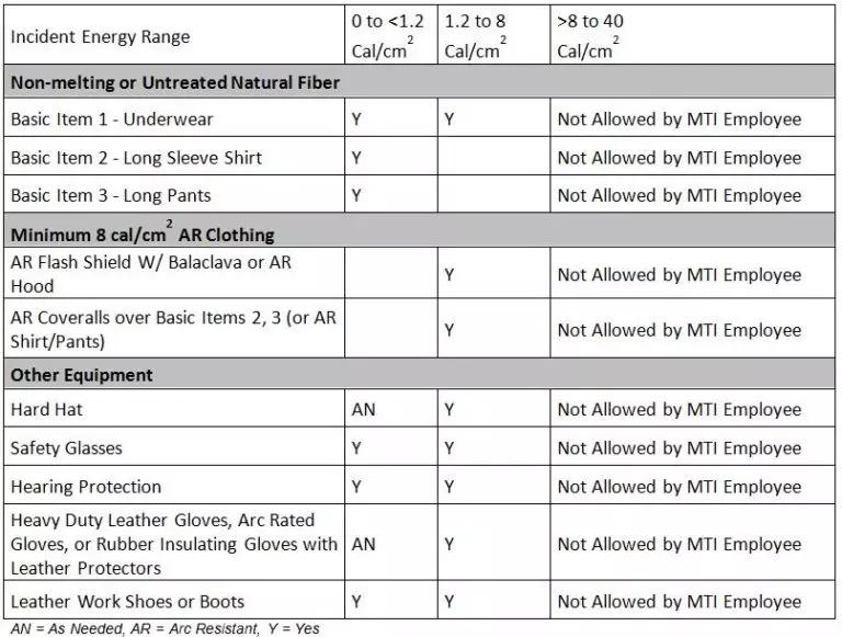
Figure 2: Example of a Simplified PPE Table
The goal of an arc flash study is to provide correct data for appropriate labeling for the electrical equipment in a facility. This labeling dictates the level of personal protective equipment that must be worn when working on exposed live parts. The arc flash study and the labels are the cornerstone of a complete electrical safety program, however, there is still a significant amount of additional effort that needs to be expended to make the program fully functional. Matrix Technologies industrial safety services engineers, highly experienced in performing arc flash studies, are available to help.
Matrix Technologies is one of the largest independent process design, industrial automation engineering, and manufacturing operations management companies in North America. To learn more about our risk assessment and industrial safety services, contact Ron Studtmann, PE, Senior Consultant, Process & Electrical Design Department.
© Matrix Technologies, Inc.


