The Critical Importance of Data Collection
Data collection is an important aspect of manufacturing engineering projects, especially at the project planning stage.
Once the project scope has been reasonably defined, engineers need to determine the best method to collect accurate data. Data also has to be collected in an efficient manner and collected safely without interfering with plant operations. In facilities construction and renovation, engineers need data that is generally dimensional in nature or used to locate existing objects. We need to locate existing buildings and structures, existing above ground utilities, process equipment, existing tie-points, and more to define how a project may interface with adjacent processes.
The days of using a camera and tape measure to collect field information are slowly diminishing. Today, there is more emphasis on choosing the right tool for the right reason.
Many years ago, Matrix Technologies, a leading manufacturing processing and automation engineering company, recognized the advantages of implementing 3D laser scanning in our engineering processes. Since many of our design engineering projects are fast-paced with a high degree of complexity, the use of a 3D scanner is an easy choice for most projects, once the benefits are understood.
The Point Cloud and Registration of Data
As explained in part 1 of this series, 3D laser scanning identifies or locates billions of data points. These data points are called the point cloud and are used to locate features of interest. Features could be elements of a building, process equipment sizes, anchor bolt locations, piping tie-points, remote utilities or ductwork hanging from above, and general dimensional relationships between multiple objects of interest.
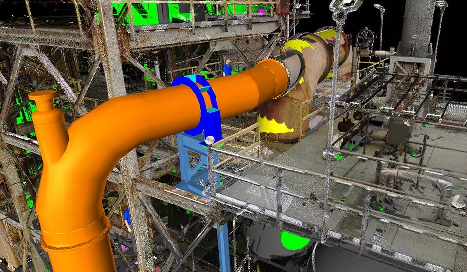
Once 3D laser scanning has been completed, multiple scans are stitched (registered) together to create a three-dimensional point cloud image of the scanned area. The point cloud is then used as a basis to integrate new work models within the existing point cloud.
3D modeling within the point cloud
5 Benefit Drivers of 3D Laser Scanning
1. Collecting More Data than Needed
When evaluating a project site for the first time, it’s likely that the exact scope of the project is still somewhat ill-defined. How often do you start a project where the position of a process is location “A,” with tie-points “B,” and maintenance access coming from position “C;” … then after initial concept layouts, you determine that the process equipment belongs in position “C” with the maintenance access from “D” and tie-points changing to position “E?”
If the traditional approach to data collection was being used, you might need to restart the initial field work.
3D laser scanning can solve this problem and help avoid the cost and time of starting over. The 3D laser scan has likely captured data points “A” through “Z” and in great detail and accuracy. This gives the engineer and owner the flexibility to make initial design changes early in the process.
Once the data is collected, the field of view of the project landscape is vastly increased compared to the traditional method of data collection, giving the engineer more options to reposition equipment or processes. This results in better decisions early in the project lifecycle.
2. Accuracy
When developing an engineering design, high importance is placed on accurate background information from the start of a project. When construction information is ambiguous, contractor field change orders can quickly add to project delays and costs.
With the advancement of data collection technology, engineers using a 3D scanner no longer need to defer to requiring the contractor to “field verify” existing field information.
The Faro Focus 3D X130 has a rated maximum range of 130 meters with a distance accuracy of +/- 2mm. Although other scanning instruments may reach further, there often is no justification to collect data past 130 meters.
Scanner accuracy is also affected by how the scanning technician traverses the work area. For example, if a technician scans the exterior perimeter of a large building, the accuracy tolerances for each scan are compounded, giving the overall scan accuracy a larger margin of error. An experienced scanning technician may utilize alternate surveying techniques to close smaller survey loops within the larger traverse, thus minimizing overall error.
3. Minimizing Travel to the Project Site
Although 3D scanning doesn’t replace traditional field work, it can greatly assist in bringing team members up to speed on a project site they have never seen. A color 3D representation of the project site also significantly enhances the perspective of a complex project for engineering team members and the owner. The point cloud and 3D active scan pictures allow the user to walk through the project site as if they were there.
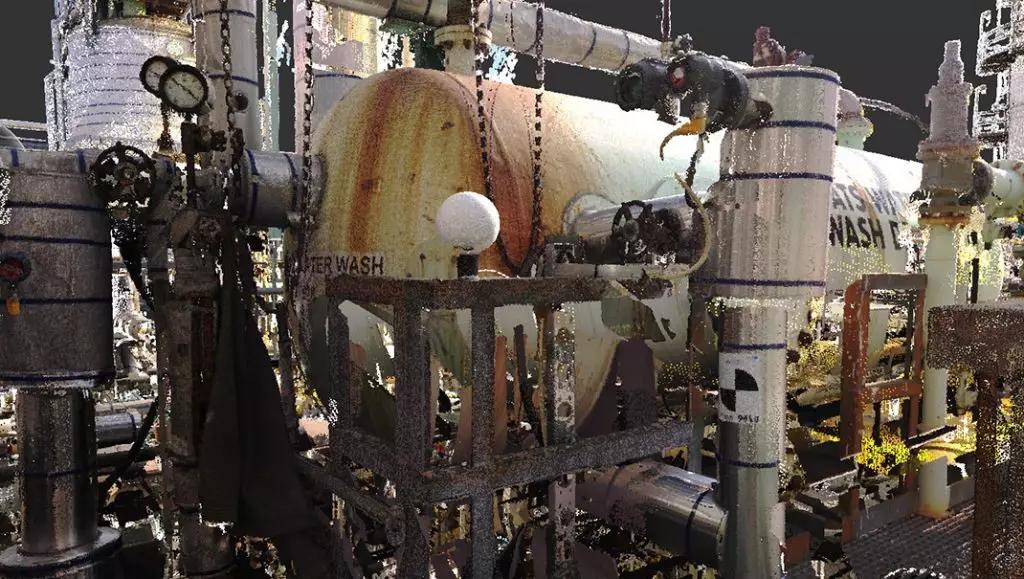
Steam Exchanger Point Cloud
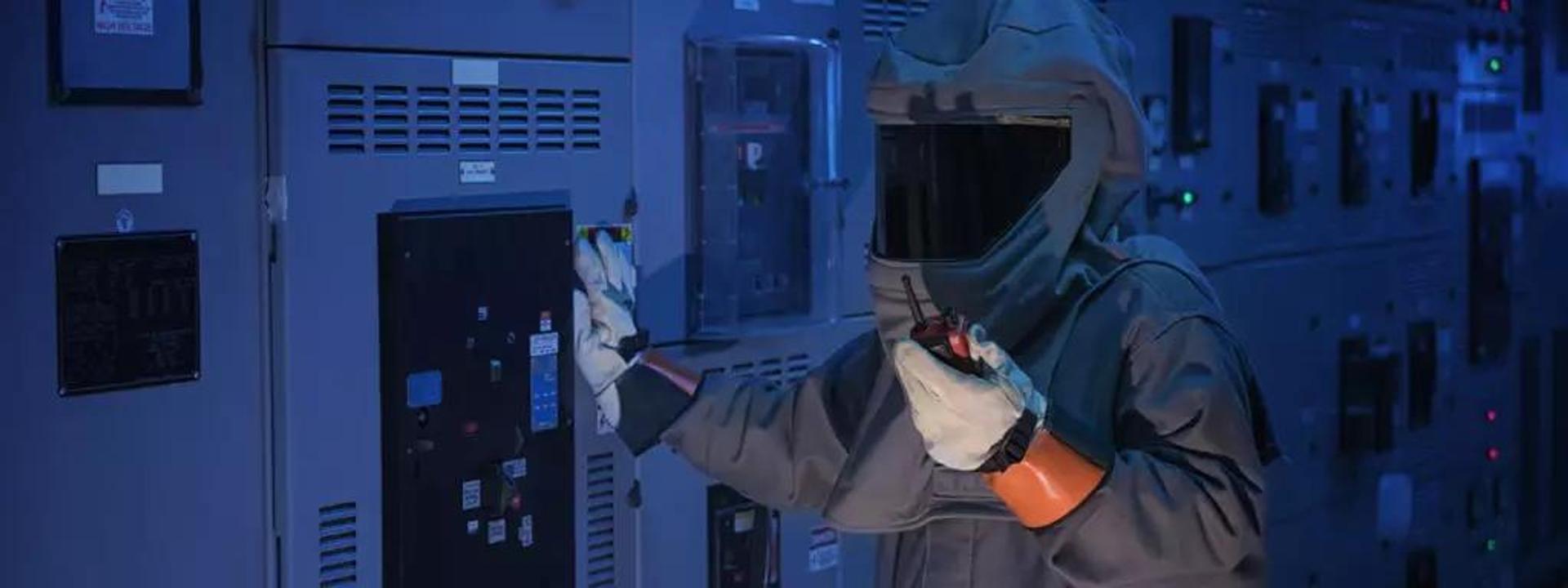
4. Safety
Since 3D scanning is performed generally from the ground level, it inherently reduces the risk of accident and injury caused by collecting data at heights and near operating equipment.
Scanner placement also can be coordinated with plant personnel to eliminate the hazards of occupying the same space as fork lifts, personnel, contractors, and other potential conflicts.
When operating a 3D scanner in a hazardous or potentially explosive area, it’s important to communicate the plan with plant operations. Most 3D scanners are not intrinsically safe and will require obtaining a hot work permit prior to starting any work processes.
5. Developing Facility as-built Documentation
Maintaining an accurate set of existing factory or plant drawings is beneficial when starting new engineering work.
However, many times there is no documentation on the existing facility, its contents, utilities, machinery layouts, and other building features. These documents may have been lost, never issued, or accidentally disposed of.
3D laser scanning is a cost-effective approach to collecting this vital data. For example, a building owner wanted Matrix Technologies to create as-built drawings for a 275,000-square foot facility that was previously used for warehousing. A new packaging process with a substantial amount of conveying was to be installed in the same area.
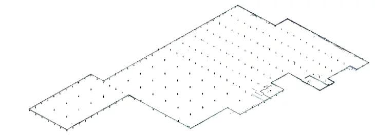
Matrix engineers performed a 3D scan of the facility and generated a point cloud. From the point cloud, we were able to take a slice through the building at any elevation.
All of the data points above and below the slice were turned off, leaving a 3D image of the outline of the walls, columns, and other objects that may have occupied the space within the slice. This simplified the data to something manageable. In AutoCAD, polylines could be drawn over the points to recreate a building outline and columns, showing as much detail as needed.
Isometric of facility showing column locations
In this example, the manufacturer realized the following benefits:
- 3D laser scanning saved thousands of dollars in engineering labor costs. Multiple individuals were not required, thus minimizing labor, travel, and other expenses.
- Since only one resource was needed to collect the data, the project was not delayed while waiting for multiple engineering resources to become available to travel to the project site.
- The data was highly accurate and allowed the new machinery and conveying to be placed on the drawing to verify interferences.
- More data was captured than originally needed. After the initial 3D scan, the customer requested that we re-measure the existing utilities in the ceiling to verify that the new machinery would not interfere with existing utilities. The scan was used to determine the sizes and elevation of the utilities to locate potential interference points. Building cross-section isometrics for utility locations and elevations were provided to the customer.
Building Cross Section Isometric
Big Benefits for Industrial Project Design
The benefit drivers for utilizing a 3D scanner far outweigh more traditional methods of collecting field data. 3D scanning tools can collect substantially more information, safely, more accurately, and in a greatly reduced timeframe. This delivers a powerful advantage to industrial automation engineering companies like Matrix Technologies and to project owners.
Matrix Technologies is one of the largest independent process design, industrial automation engineering, and manufacturing operations management companies in North America. To learn more about our 3D laser scanning services and multidiscipline engineering solutions, contact Mark O’Connell, PE, Associate Director of Capital Project Planning.
Click here to read Part 1: Using 3D Laser Scanning in Industrial Plant Design
Click here to read Part 3: 5 Crucial Estimating Scanning Costs
© Matrix Technologies, Inc.