Using 3D Laser Scanning in Industrial Plant Design
Mark O'Connell,
Associate Director of Capital Project Planning
Advances in technology have dramatically improved quality and lowered costs for industrial automation engineering companies that design and build manufacturing facilities.
One of the latest advances is 3D laser scanning. Here’s an overview of how 3D laser scanning can enhance engineering accuracy, shorten project schedules, and improve coordination between engineering project teams and manufacturers.
The Evolution of Surveying Technology
Data collection technology was once a slow, labor-intensive operation with multiple technicians collecting field data using manual tape measuring devices, and pencil-to-paper data recording. The information collected was the starting point or canvas for a new building, process, or other infrastructure project. Field information was then delivered to the engineering office, where a second team of engineers and designers would assimilate the information and recreate existing topographic plans on drafting boards. Multiple surveying technicians transferring messy field information to an office technician who’d never been to the project site would many times lead to confusion and mistakes.
Back then, data collection technology was limited, cumbersome, and prone to mistakes.
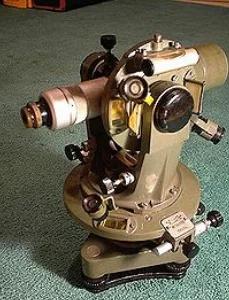
Reflecting back on my earlier days spent collecting field data, I vividly remember performing topographic surveys with a three-person team. Two members of the team were responsible for the chain (or linear tape measure generally 100’ long), while a third operated the theodolite or instrument used to measure horizontal angles and vertical planes.
Once the baseline was established, two people determined the location of site objects by measuring the distance from the baseline using a handheld 90-degree prism and recording the station point from the baseline. It took a substantial amount of effort to collect a minimal amount of data with relatively low accuracy.
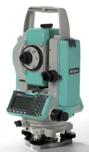
The next step in the evolution of data collection was the mainstream use of Total Stations, or electronic distance measurement devices (EDM), in the 1990s. The EDM would pulse a laser beam to a reflective prism, then calculate the distance based on frequency and wavelength of the returning signal. Data from the survey could either be stored on the EDM or on a handheld data collector.
If you owned a typical Total Station, you likely had a two-person crew: one to operate the EDM and one to walk the reflective prism to locate objects. These EDMs had much greater accuracy and were able to download data points directly into CAD software. Later, more expensive versions of the instrument could be operated by single users. The EDM is still in use today due to its high accuracy which is required for surveying needs. However, for the collection of topographic information, the EDM can be slow as it reads only one data point at a time.
The 3D laser scanner survey came along in the 1990s but was not mainstream until after 2000. Like any new technology, entry-level price points were prohibitive. In addition, point cloud file sizes were generally too large to store and transfer between users.
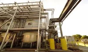
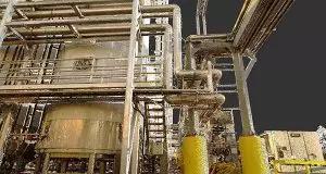
The 3D laser scan is used to capture data information on existing structures, equipment, utilities, or manufacturing processes. 3D scanning will capture dimensional information on any existing objects or surfaces. Once this data is acquired, a point cloud is generated and used as the background or basis for a design.
How a 3D Laser Scanner Works
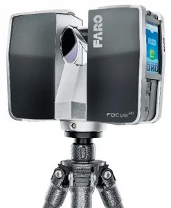
Faro 3D Scanner
Similar to a Total Station, a 3D scanner projects a laser onto a surface, which is then reflected back to the scanner. The scanner will analyze and compare the differences in reflected light frequency and the phase shift of the reflected wavelength to determine the object’s position in space.
The 3D scanner contains an internal mirror that rotates vertically in a full circle. In addition, the scanner will rotate horizontally in a full circle. This combination of a vertically- rotating mirror and horizontally rotating scanner produces a 3D point cloud in a sphere emanating from the scanner.
Target Arrangements
The value of a point cloud is to collect data-point information from all sides of an object. To do this, the scanner collects data information from multiple positions around that object. During the registration process, the software will “stitch” these scans together, creating one larger point cloud comprised of multiple scans.
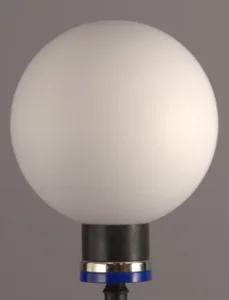
The scanner uses reference points, or targets, which are of known size and placed in the field-of-view during the scanning process. When the first scan is complete, the scanner is moved to scan position 2. The new placement must see at least three targets that were present in scan position 1. Three new targets are placed for the second scan, leaving six targets in the field, three of which are known to scan position 1. When the second scan is performed, scan positions 1 and 2 are tied together from the three initial spheres.
The scanning process continues, leapfrogging previously-scanned targets so there are always three reference spheres that were located in the previous scan. Depending on the complexity of the project, the final point cloud (which is created from the multiple scans) could be over 100 scans, each stitched together through the registration process.
Color Photographs
After completing the initial scan, the 3D scanner performs a second 360-degree rotation. During this event, the scanner will take color photographs of the previously scanned area. Each scan will include 85 color photos, which can be used by both the engineering team and the manufacturer to relay visual information to team members who are not on site, and to facilitate and coordinate design discussions.
Scan Resolution
The quality (or resolution) of a scan determines the spacing between points, which determines the level of detail. As the scanning technician increases the scanning resolution on the instrument, more data points will be collected for an increased point-cloud density.
Generally, increased point density (resolution) improves the quality of the point cloud. Increased point density also adds to laser scanning time, as the laser moves at a slower pace to collect the increased number of data points. In addition, the final point cloud for a higher resolution will have substantially more points, thus increasing the overall file size.
Scanning Distance
Every 3D scanner has a maximum distance from which it can collect data. For example, the Faro Focus 3D X-130 has a maximum range of 130 meters, with a distance accuracy of +/- 2 mm. Unless the user is scanning tall buildings or long bridges, selecting a scanner with an extremely long scan range may not be needed for a typical project scan. More likely, the scanner has captured too much, or irrelevant data beyond your area of interest. Most of these irrelevant data points will be deleted during the data registration phase to simplify the point cloud and the reduced point-cloud file size.
Out With the Old, In With the New
Looking back on my early surveying days, I wonder how we could collect so little data with so many people for a price that was competitive. A crew of three would average 50 linear feet per man-hour to set the baseline and collect general topography information using a theodolite and traditional surveying tools.
Today, using 3D laser scanning technology, a scanning technician can collect substantially more information, more accurately, and have it completed in a greatly reduced timeframe, delivering powerful advantages to industrial engineering companies and project owners.
Matrix Technologies is one of the largest independent process design, industrial automation engineering, and manufacturing operations management companies in North America. To learn more about our 3D laser scanning services and multidiscipline engineering solutions, contact Mark O’Connell, PE, Associate Director of Capital Project Planning.